Connecting LED fixtures: First steps
The next steps will guide you in order to both install the Controller and its Satellites, as well as wire them to the LED lighting.
Note
If you have problems, please relate to the section Troubleshooting. Especially if getting Color Noise, as it can get might be tricky.
Note
It is important to double-check the LED and power supply wiring. Use this manual as a reference, and follow step by step all instructions described below.
Caution
The Controller has three RJ45 ports one with LED indicators for the network connection and two for the connection to the satellites. Do not connect your network cable to the satellites’ ports, it could damage your network infrastructure.
Note
LED fixtures are sold separately, you can use any WS2811 or ws2812 based LED fixture. They can be acquired at our webshop: https://shop.protopixel.net as well as the basic needed material for your setup.
This guide will show you how to make all connections, wirings and configurations in four steps.
Step summary:
| Step | Description |
|---|---|
| 1 | Wiring Led’s data signal to the PPx satellite |
| 2 | Powering the LEDs |
| 3 | Connecting the controller |
| 4 | Configuring the controller |
Wiring Led’s data signal to the PPx satellite
In order to connect your fixture to the satellite you should find the data and ground wires located at the beginning of your fixture (data-in or din).
Caution
Check your LED fixture’s documentation or datahsheet to ensure which wire is the data (usually green) and which one is the ground (usually blue).
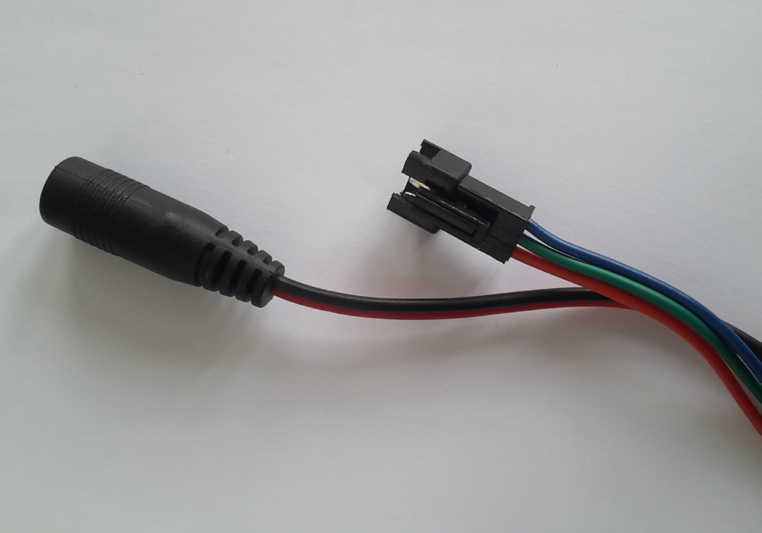
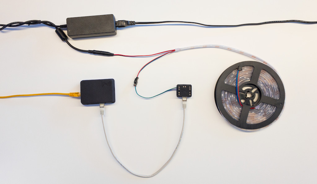
Example of a Data connector and a power jack attached to a LED strip
JST 3-pin aerial connectors are the most common used for addressable LED Strips. The connector could be either male or female according to your LED strip provider. These connectors use to be accompanied by a power jack or two wires for providing a separated source of power to your led fixture.
Note
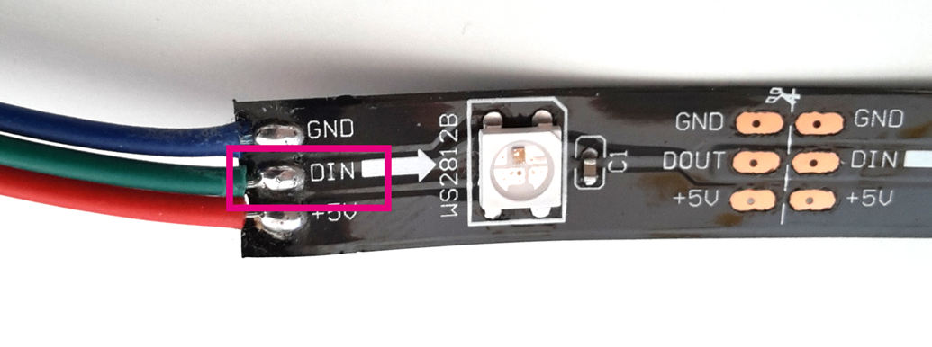
To find the beginning of an addressable led strip check the little arrow(s) printed on the strip in order to get the direction of the data signal. Another effective way to find it by locating a printed “din” or “di” on your fixture.
Caution
In the shown examples, Data pin (DIN) appears as a green wire and GND pin as a blue wire. Notice that the customer’s LED lighting connectors may display a different wire colour code. Check always the datasheet or documentation of your fixture.
Example of the location of the Data IN (DIN) pin (green wire in our example).

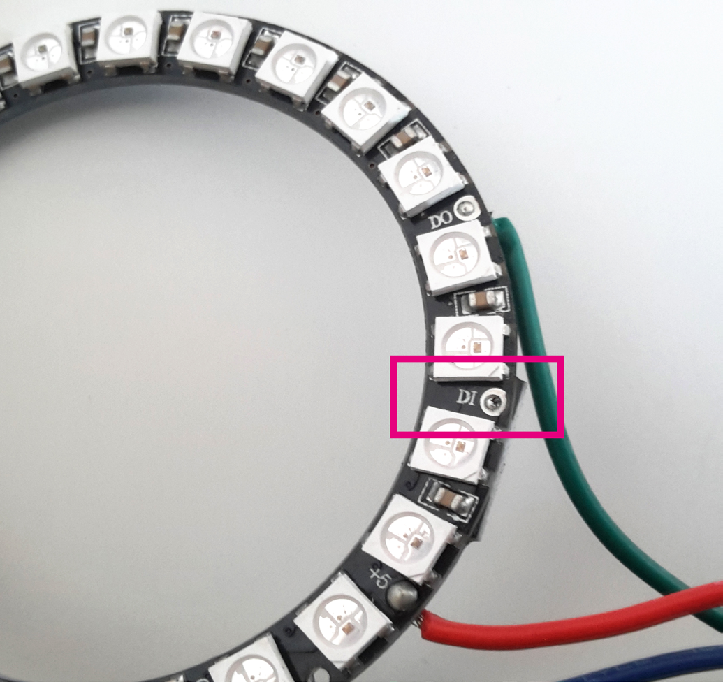
Example of the location of the Ground (GND) pin (blue wire in our example).
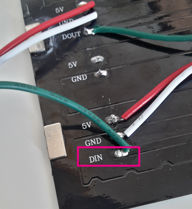
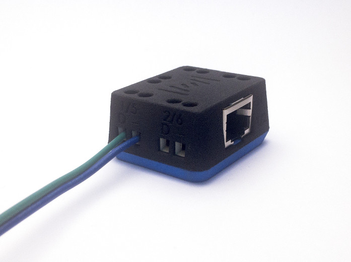
Within the LED lighting package it is common to find a 3-pin connector that matches the connector attached to the LED strip. Wire the two cables, Data-in and Ground to the Satellite as shown in the following images:
Caution
Make sure that the data wire is the one located at the left side of the connector and the gnd wire is the one at the right side.
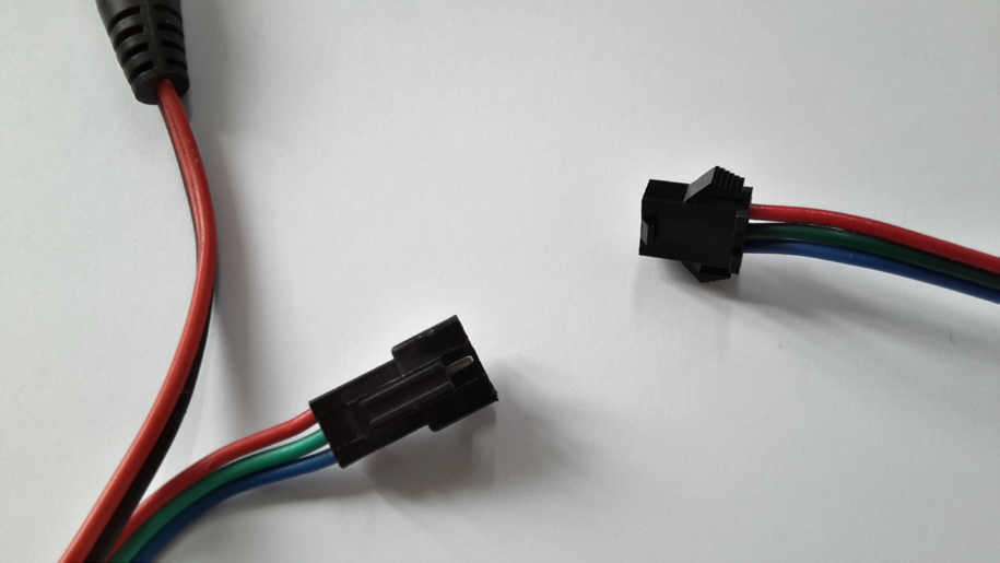
Example of the male and female connectors.
That’s all!! your first led strip has been wired and it is ready for receiving data!
Powering the LEDs
There exist different types of power supplies: Enclosed, Din rail, Power rack or adaptors. In this section we will focus on AC/DC adaptors and enclosed power supplies as they are the most common used on small and medium-large LED installations. The following instructions describe how to wire a power supply to the AC power outlet.
Adaptors
AC/DC adaptors are the easiest way to be used on small installations. They tend to be compact, provided with all the wires and connectors and if you correctly chose the one that fits on your fixture, plug and play.
The bad side of these power supply is that they are not powerful enough for powering a large set of LED’s.
To use them it is only required to connect first the power-jack to the LEDs and after that the power plug to the power outlet.
Warning
A common mistake with these power supplies is the choice of an underpowered unit. Make always sure that the volts and Watts are the right for your LED fixture, otherwise your fixture could be damaged and your power supply overheated.
Enclosed power supply
Enclosed power supply are the most common used on medium and large LED installations. They drive a lot of power and exists different models depending on the brand and the place where they will be located (exterior, interior, refrigerated areas, …)
Danger
Enclosed power supplies have the power terminals and contacts exposed, do not manipulate them unless you are sure what are you doing. If necessary contact an electrician or let an expert do it for you.
Warning
If your installation requires more than one power supply, read carefully the power supply datasheet or contact a qualified operator. These devices could be dangerous if are wrong wired or bad isolated.
Note
As a recommendation, to prevent a power loss we suggest to locate the power supplies as close as possible to your LED fixture. Doing this colour degradation will be avoided.
Wiring an enclosed power supply to the power outlet
The following instructions describe how to wire a power supply to the AC power outlet.
Caution
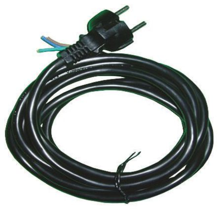
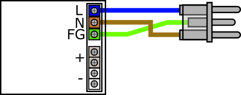
Carefully follow the instructions to ensure all power cables are correctly installed. Whether the AC power cord does not come with an installed plug, ensure when installing that the terminals are well connected (AC/L (blue), AC/N (brown) and FG (Green and yellow) ).
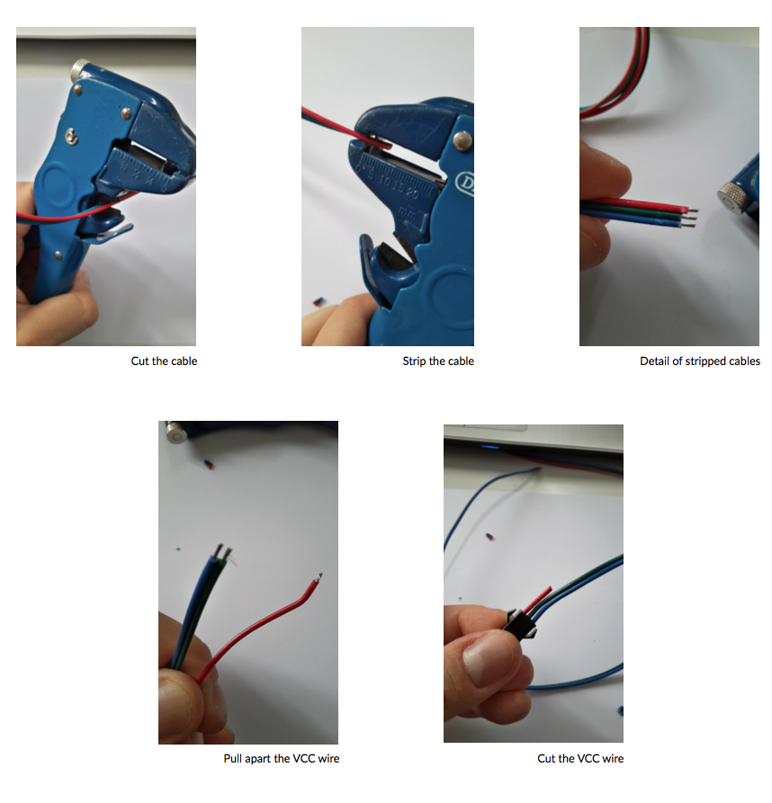
To install the power cord you should strip the free end of the AC power cord. To do that, separate the different AC wires enough and strip the ends of each one.
Note
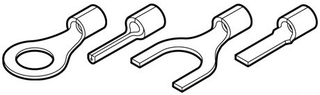
We strongly recommend the use of Crimp Terminals to prevent shorts between power supply ports and the exposed metallic areas
Connect each of the 3 wires to the power supply terminals following the same colour code as shown at the scheme:
Danger
Make sure to correctly follow these wires color code. If wrong connections are made, ProtoPixel Controller, LED lighting fixtures and power supply could be damaged.
Wiring an enclosed power supply to the LED fixtures
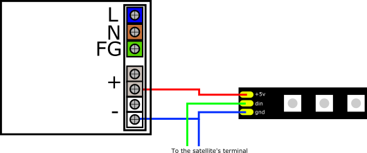
As shown before, LED fixtures are usually accompanied by a power jack or two spare wires (positive and negative) that are meant to provide power to the LEDs. Enclosed power supplies have one or more positive and negative terminals for connecting the fixtures.
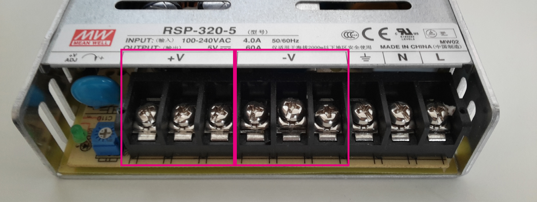
Example of the positive and negative terminals of an enclosed power supply.
Configuring the controller
By default each ProtoPixel device is configured to get an IP address by DHCP. When an IP address is not assigned by a DHCP server, the controller uses an static IP like 192.168.133.XXX with the netmask 255.255.0.0. Each device has an internal non volatile memory to store different connection and fixture parameters, the following table shows the information stored in this memory which is used to configure the device. The manipulation of those parameters has to be done trough the Protopixel create refer to Connecting a Controller to a Device.
| Parameter | Description |
|---|---|
| Network configuration | |
| Static IP | IPV4 address of the device used when DHCP not available |
| Static Gateway | Network Gateway used when DHCP not available |
| Static Mask | Network Mask used when DHCP not available |
| DHCP | Enable or disable DHCP (toggle on/off) |
| Device behaviour | |
| Test Leds | Enable or disable test leds at the beginning (toggle on/off) |
| Notification LED | Enable or disable notification LED (S1)(toggle on/off) |
| Device name | Name of the device |
Connect to the network
ProtoPixel is a plug and play device. Once it is switched on, the device connects to the configured network and it is automatically discovered by the ProtoPixel software. Step by step connection Ethernet:
- Plug the 10/100 ethernet connector to the controller’s ethernet port.
- Connect the other cable edge directly to a computer or through a networking device like a switch or router via a local network.
- Connect the Light Fixtures to the fixture ports.
- Connect the power jack to the ProtoPixel Controller.
- The device is automatically discovered by the ProtoPixel software.
- Power the light fixtures separately.
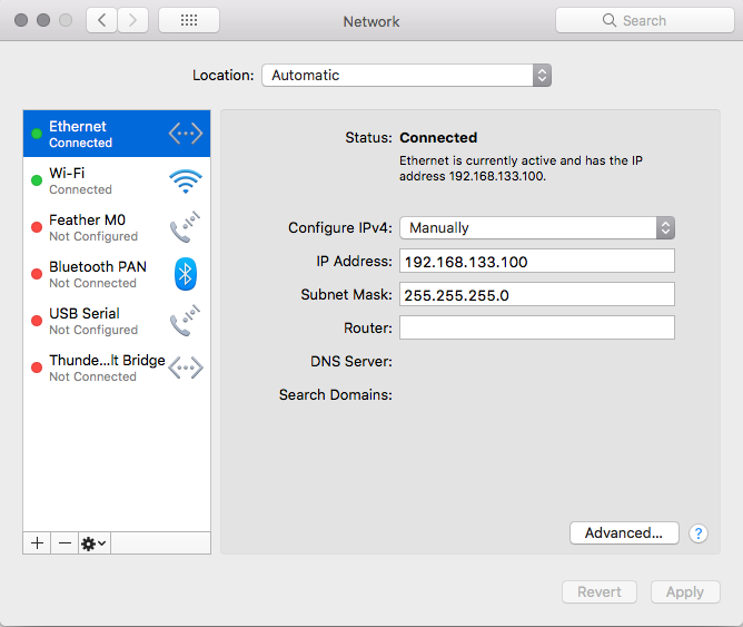
Direct connection from your computer to the ProtoPixel controller
If you are trying to connect the controller directly to the ethernet port of your computer or using the controller with an static IP you should configure your network interface. By default the controller is configured with an IP inside the subnet 192.168.133.XX with the mask 255.255.255.0. To setup your OSX system you can reach the network configuration by going to System preferences -> Network -> Select your ethernet port and modify from using DHCP to Manually.
Send Light information
At this point the device is powered up and running and can receive input from different Lighting programs, scripts or syphon by using the ProtoPixel Software.